HP 3478A multimeter: a new display and the missing continuity beep
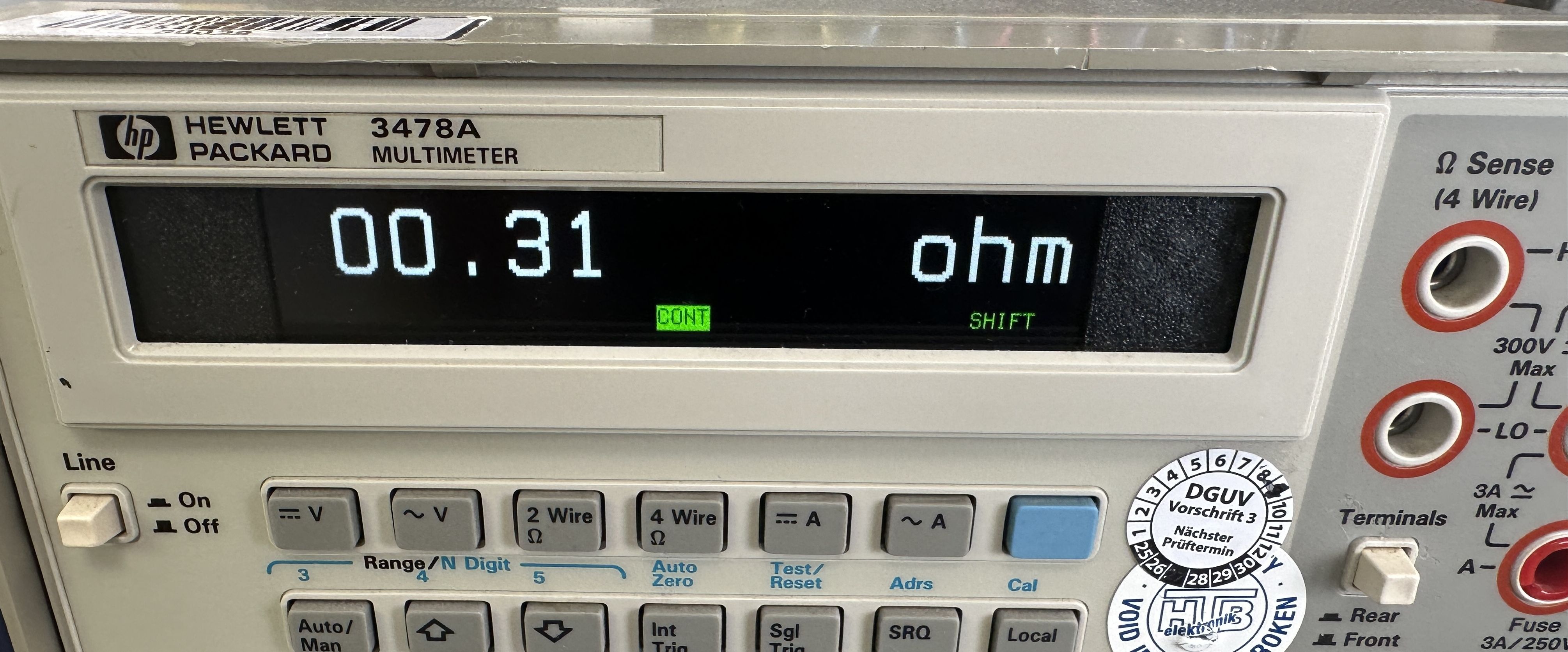
The HP 3478A is one of those instruments you simply can't go wrong with: a 5.5 digit bench multimeter with GPIB, built like a tank and still available for small money on the used market. Mine has been serving faithfully on the bench for years. But there is one shortcoming which bugs me every single time I reach for it: HP saved the beeper! The 3478A has no continuity function whatsoever. Chasing broken traces or ringing out a cable harness with your eyes glued to the display while poking around with the probes is just no fun. Every cheap handheld meter can do better here...
Ian Johnston's TFT display replacement
My 3478A had already received the display treatment some time ago: Ian Johnston designed a beautiful TFT replacement for the stock LCD, which is notorious for fading with age. The concept is really clever: a "Blue Pill" STM32F103 board sniffs the serial bus between the meter's CPU and the original display controller, decodes the reading and all annunciators on the fly and redraws everything on a modern 960x240 bar-type TFT which is driven by a LT7680A-R controller board. No modification to the meter's electronics at all, the thing just listens passively to what the meter wants to show.
One hint for fellow converters: on my particular unit the +5V supply for the display turned out to be fed through R506, a 1k series resistor on the main board. That's perfectly fine for the trickle the original display electronics draw, but it starves the Blue Pill and TFT of the conversion. Bridging R506 solved it - check your schematic revision before hunting elsewhere if the new display doesn't come to life.
All credits for this great project go to Ian Johnston! You can find his video blog, the gerbers for the interface PCB and the STL files for the 3D printed bezel on his homepage:
https://ianjohnston.com/index.php/conversions/video-blog-176-3478a
The idea
One evening it struck me: the Blue Pill already knows everything the meter displays - the reading, the unit and all annunciators. So all the ingredients for a continuity beeper are already sitting right there in the decoded display data! No additional wiring into the meter, no messing with the analog section, just a firmware modification and a small buzzer on one of the free STM32 pins.
How it works
The continuity mode is armed with the meter's SHIFT key: pressing SHIFT latches the shift annunciator on the display (until you press it again), so it conveniently doubles as an on/off switch for the beeper - no free button required. When the meter is in resistance mode (2- or 4-wire), shift is latched and the parsed reading is at or below 10 Ohm (a define in main.h, adjust to taste), the beeper sounds. As visual feedback the lit 2ohm/4ohm annunciator on the TFT turns into an inverted "CONT" - black text in a green box - while the beeper is active.
The firmware parses the decoded display string with a small hand-rolled fixed point parser (newlib's strtod would have dragged approx. 15kB of float code into the flash...), guards against corrupted frames and overload readings and debounces the on-transition by one frame so a single bad decode can't chirp the buzzer.
For the hardware side you get both connection options on two neighboring pins, conveniently located right next to GND and +5V on the Blue Pill header. I added a JST receptable so I can connect a small speaker:
. PB8 goes static high while continuity is detected - for an active (self-oscillating) buzzer
. PB9 outputs a 1kHz square wave - for a passive buzzer or piezo disc
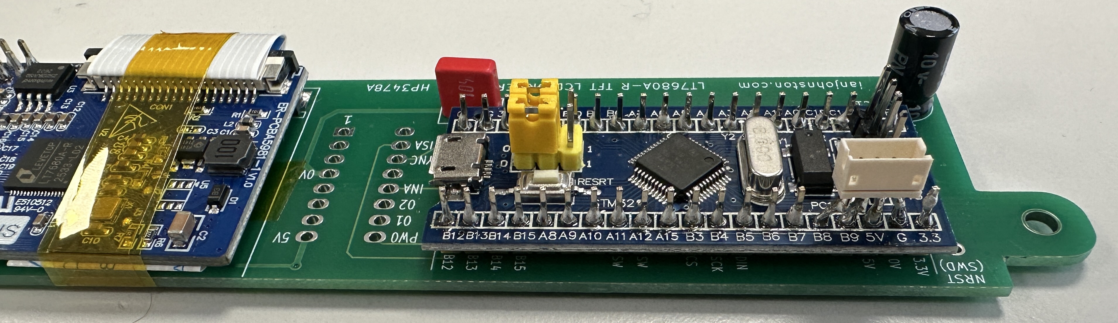
The square wave comes for free from the hardware: PB9 happens to be TIM4 channel 4, so the timer free-runs at 1kHz PWM and the firmware just gates the tone through the compare register. No interrupt, no CPU load, no interference with the timing critical display bus capture. Both pins can only source a few mA, so use a small NPN transistor if your buzzer is thirstier.
Firmware archaeology - the fun part
Of course it wasn't as straightforward as it sounds, the way to a reliable beep was paved with lovely little traps. As Ian's project ships as a VisualGDB / Visual Studio solution and I'm on a Mac, the first step was a plain Makefile using the official Arm gcc toolchain, flashing is done with an ST-Link V2 and the open source st-flash tool. For the detective work I have to admit I had AI support - Claude Code did a lot of the heavy lifting here, including live RAM dumps from the running meter over SWD which unveiled the nastier surprises below :-)
The letter-digit charset collision: the first version of the parser simply refused to beep on a dead short. A RAM dump of the decoded display string revealed why: a 0.1885 Ohm reading arrives as " OO.188S OHM"! The 3478A's character set shares one code between the digit 0 and the letter O and another one between 5 and S. On the TFT this is invisible as O renders just like 0, but a parser looking for digits finds... none. Funnily enough, Ian's firmware already contained the same quirk from the other side: the meter's self test message arrives as "5ELF TE5T" and gets patched for display. So the parser now translates O and S back to 0 and 5 before parsing.
The O.VLD trap: after fixing the letter-digits, the beeper suddenly kept beeping with open leads, ouch! In overload the meter displays OVLD but keeps the decimal point segment of the current range lit, so the decoded string actually reads "O.VLD" - which slips past a simple OVLD string match, and thanks to the fresh O-to-0 translation the parser happily reads it as 0.0 Ohm. Phantom continuity on open leads, the perfect inversion of the intended function :-) The fix: match OVLD and the units against the punctuation-free display string and only parse the value from the punctuated one.
The flickering annunciators: with the beeper working I noticed the lit annunciators flickering at their edges. Turned out to be a race in the display driver itself: the LT7680 renders text asynchronously after the characters have been queued, and the original DrawText returned immediately. With twelve annunciator draws back to back, the next draw's colour registers landed while the previous string's tail was still being rendered - so the tail got painted in the wrong colours. Draining the controller's "core busy" status flag at the end of DrawText fixed it for good.
As a bonus the firmware now shows a short colour cycling splash on power-up. Previously a board without a meter attached showed nothing but a black screen, which makes bench testing rather unrewarding...
Usage tip: make it respond faster
The beeper can only react as fast as the meter updates its display, so the reading rate directly sets the beep latency. Two things help a lot: lower the meter's resolution to 3.5 or 4.5 digits (fewer integration cycles, faster readings) and/or lock the meter into a fixed low resistance range instead of autoranging - hunting through the ranges with open leads costs several display updates before the short is finally displayed. With reduced resolution and a locked range the beeper responds quickly enough for comfortable harness ringing.
Download
Here you can
download the complete modified firmware source including the Makefile for building on macOS/Linux with the Arm gcc toolchain, flashing notes for the ST-Link V2 and the documentation of all the findings above. The continuity threshold lives in Core/Inc/main.h (CONTINUITY_THRESHOLD_OHMS, default 10 Ohm). Build it, flash it via SWD, connect a buzzer between PB8 (active type) or PB9 (passive type) and GND - and enjoy a 40+ year old multimeter that finally beeps :-)
And once more: the display replacement itself including PCB gerbers, bezel STL and installation videos is Ian Johnston's work, please visit
his project page for everything needed for the base conversion.
(c) DJ9KW